 EN
EN
Shengan Building A, Hengzeng Road Chang'an Town Dongguan City,
Guangdong, China, Zip Code: 523880
Die casting produces net-shape metal components with dimensional accuracy, surface finish, and production speed that few other metal forming processes can match. From automotive structural parts and electric vehicle battery housings to consumer electronics chassis and industrial valve bodies, die casting delivers complex geometries at cycle times of seconds — not minutes or hours.
At the center of this process is the die casting mould: a precision tool that must withstand molten metal injection at pressures exceeding 100 MPa and temperatures above 700°C (for aluminum), while maintaining dimensional stability across hundreds of thousands of shots. The quality of the mould design determines part quality, production efficiency, and total manufacturing cost more than any other single factor.
This guide covers the essential design principles, material-specific considerations, and practical decision-making frameworks for die casting moulds across aluminum, zinc, and magnesium alloys — with particular attention to sourcing from a die casting mould china manufacturer.
The dominant method for volume production. Molten metal is injected into a steel mold cavity at high velocity (20–80 m/s gate velocity) and high pressure (40–120 MPa). Solidification occurs in seconds, and the part is ejected automatically.
Best for: High-volume production (1,000+ parts), complex thin-wall geometries, tight tolerances
Alloys: Aluminum (A380, A383, A360, ADC12), Zinc (Zamak 3, 5, 2), Magnesium (AZ91D, AM60B)
Part size range: 10 g to 50+ kg depending on machine capacity
Molten metal is fed into the mold cavity through a riser tube using low gas pressure (0.2–0.5 bar). Gravity and pressure combine to fill the cavity more gently than HPDC.
Best for: Thicker-wall parts, structural components requiring high integrity, automotive wheels
Surface finish: Not as fine as HPDC
Porosity: Lower than HPDC due to gentler fill
Molten metal is poured into a metal mold under gravity. No external pressure is applied.
Best for: Low-to-medium volume, thicker sections, simpler geometries
Tooling cost: Lower than HPDC molds
Surface finish: Good but not comparable to HPDC
This guide focuses primarily on HPDC mold design, as it represents the largest segment of industrial die casting.
| Property | Aluminum (A380/ADC12) | Zinc (Zamak 3) | Magnesium (AZ91D) |
|---|---|---|---|
| Density (g/cm³) | 2.74 | 6.60 | 1.81 |
| Melting range (°C) | 540–595 | 380–390 | 430–600 |
| Typical wall thickness (mm) | 1.0–3.0 | 0.5–2.0 | 0.8–2.5 |
| Tensile strength (MPa) | 320–330 | 280–290 | 230–250 |
| Elongation (%) | 3–4 | 7–10 | 3–5 |
| Die life (shots) | 100,000–300,000 | 500,000–1,000,000+ | 50,000–150,000 |
| Machinability | Good | Excellent | Good |
| Corrosion resistance | Moderate (needs coating) | Good (natural patina) | Poor (needs coating) |
| Typical cost/ton | Moderate | Moderate | High |
Aluminum — The default choice for automotive, industrial, and consumer electronics applications where strength-to-weight ratio, corrosion resistance (with surface treatment), and recyclability are priorities. Dominates EV structural components, thermal management housings, and general-purpose mechanical parts.
Zinc — The precision alloy. Lower melting point means dramatically longer die life and the ability to cast extremely thin walls (0.5 mm). Best for complex, tight-tolerance parts with excellent surface finish: decorative hardware, electronic connectors, miniature mechanisms, and any application where as-cast finish quality is paramount.
Magnesium — The lightest structural metal. At 1.81 g/cm³, it is 34% lighter than aluminum and 73% lighter than zinc. Used where weight savings justify the higher material and processing cost: aerospace components, high-performance automotive, portable electronics housings, and EV battery enclosures.
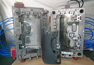
A die casting mould consists of two primary halves:
Cover half (fixed die): Contains the gate, runner system, and one side of the cavity. Mounted to the fixed platen of the die casting machine.
Ejector half (moving die): Contains the other side of the cavity, ejector system, and any core slides. Mounted to the moving platen.
The mould is built from several layers:
| Component | Material | Function |
|---|---|---|
| Mold base | Medium carbon steel (S50C, 1045) | Structural frame, mounting to machine |
| Cavity inserts | H13, 8407, SKD61, or maraging steel | Forms the part geometry; bears direct contact with molten metal |
| Core pins | H13 or tungsten carbide | Internal features, bosses, holes |
| Slides and core pulls | H13 or hardened tool steel | Side-action features for undercuts |
| Ejector pins and plates | Nitrided steel | Part ejection after solidification |
| Guide pins and bushings | Bearing steel | Alignment of mold halves |
| Steel Grade | Hardness (HRC) | Best For | Die Life (Aluminum) |
|---|---|---|---|
| H13 | 44–52 | General-purpose aluminum die casting | 100,000–200,000 shots |
| 8407 (modified H13) | 44–52 | High-thermal-fatigue applications | 150,000–300,000 shots |
| SKD61 | 44–52 | Asian-market equivalent of H13 | 100,000–200,000 shots |
| Maraging steel (18Ni300) | 50–54 | Premium applications, complex geometries | 200,000–500,000 shots |
| Tungsten carbide (inserts) | 70+ | High-wear areas (gates, cores) | Significantly extends wear life |
For zinc die casting, die life is dramatically longer (500,000–1,000,000+ shots) due to the lower casting temperature. Standard H13 is more than adequate for most zinc applications.
The gate delivers molten metal from the runner into the cavity. Gate design directly affects fill pattern, air entrapment, porosity distribution, and surface finish.
Gate types:
| Gate Type | Description | Best For |
|---|---|---|
| Edge gate | Rectangular opening at parting line | General-purpose, flat parts |
| Tangent gate | Angled entry directing flow along wall | Box sections, tubular parts |
| Pin gate | Small circular opening | Small parts, multi-cavity layouts |
| Ring gate | Annular opening around a core | Cylindrical parts, bearing housings |
| Submarine (chisel) gate | Below parting line, automatic degating | High-production parts where manual degating is undesirable |
Gate design principles:
Gate area should be sized to achieve target gate velocity (25–50 m/s for aluminum, 20–40 m/s for zinc)
Gate thickness is typically 50–80% of the adjacent wall thickness
Position the gate to promote unidirectional fill and avoid trapped air pockets
Avoid directing flow perpendicular to a core pin (causes core deflection and porosity)
The runner connects the machine nozzle or biscuit to the gates. For multi-cavity molds, the runner must be balanced so all cavities fill simultaneously.
Trapezoidal cross-section is standard — easy to machine and provides good flow characteristics
Runner volume should be minimized to reduce recycle/remelt cost
Balanced runner layouts are essential for multi-cavity molds — unequal fill causes dimensional variation between cavities
Overflows are pockets designed to capture the first metal to enter the cavity, which carries air and lubricant residue. Proper overflow design reduces porosity and improves surface finish.
Volume: Typically 10–30% of part volume, distributed around the cavity periphery
Location: At the end of fill paths, at blind pockets, and at thick-to-thin transitions
Connection: Connected to the cavity by thin channels that freeze off quickly
Vents are narrow channels (0.05–0.15 mm deep) that allow air to escape from the cavity ahead of the metal front. Without adequate venting, air entrapment causes blow holes, blistering, and surface defects.
Die temperature control is critical for part quality, cycle time, and die life. Cooling channels circulate water or oil through the die to extract heat from the casting.
Design principles:
Cooling channels should be placed as close to the cavity surface as practical (typically 15–25 mm distance)
Conformal cooling channels (made possible by 3D-printed die inserts) follow the cavity contour and provide 20–40% faster cycle times compared to straight drilled channels
Maintain uniform die temperature across the cavity — hot spots cause surface defects; cold spots cause misruns
Multiple independent cooling zones allow differential temperature control
The casting must be ejected cleanly after solidification without deformation, sticking, or cracking.
Ejector pins: Standard method — round pins push the part off the core. Position pins on non-critical surfaces wherever possible
Ejector sleeves: For ejecting around core pins (boss features)
Blade ejectors: Thin, flat ejectors for rib sections
Air ejection: Compressed air assists mechanical ejection for thin-wall parts prone to sticking
Aluminum alloys are cast at 620–700°C, imposing severe thermal cycling on the die. Thermal fatigue (heat checking) is the primary failure mode —表现为网状裂纹出现在型腔表面.
Design recommendations:
Use premium-grade H13 or 8407 steel with strict hardness control (46–50 HRC for general applications)
Minimize sharp corners and stress concentrations in cavity geometry — fillet all internal corners with minimum R1.5
Implement generous cooling to maintain die surface temperature between 200–300°C
Plan for surface refurbishment (polishing, welding) at 30,000–50,000 shot intervals
Apply surface treatments (PVD TiAlN, nitriding) to extend die life by 30–50%
Zinc alloys are cast at 380–420°C — substantially lower than aluminum. This lower temperature dramatically reduces thermal fatigue, resulting in much longer die life.
Design recommendations:
Standard H13 at 44–48 HRC is more than adequate
Wall thickness can be as thin as 0.5 mm — design accordingly for maximum weight savings
Surface finish quality is excellent as-cast — design the cavity surface finish to match the final part requirement (polished, textured, or as-machined)
Overflows can be smaller than aluminum due to lower oxidation tendency
Magnesium is cast at 620–680°C, similar to aluminum, but has unique properties that affect mould design:
Lower volumetric heat capacity means the die heats up faster — requires more aggressive cooling
Reactivity with water — die cooling systems must be thoroughly sealed; water leaking into molten magnesium is a serious safety hazard
Lower viscosity than aluminum at casting temperature — fill velocity is higher, requiring careful gate and vent design to avoid air entrapment
Shorter die life than aluminum due to higher thermal fatigue and erosion at gates — consider premium steel grades and protective coatings
Porosity is the most pervasive quality challenge in die casting. It takes two forms:
Air or lubricant vapor trapped in the casting during high-speed fill.
Mould design countermeasures:
Optimize gate velocity and fill pattern to promote progressive, unidirectional filling
Increase overflow volume at end-of-fill locations
Maximize vent area — ensure total vent area is at least 50% of total gate area
Consider vacuum-assisted die casting (vacuum valve integrated into the mold) for critical structural parts
Metal contracts during solidification, creating voids in the last areas to freeze — typically thick sections, intersections, and isolated bosses.
Mould design countermeasures:
Maintain uniform wall thickness — avoid abrupt transitions from thin to thick
Use squeeze pins (intensification pins) that apply pressure to isolated heavy sections during solidification
Optimize cooling channel placement to direct solidification from thin to thick sections (directional solidification)
Add local chills (copper or beryllium-copper inserts) at heavy sections to accelerate local cooling
| Mold Type | Cavities | Indicative Cost Range | Typical Lead Time |
|---|---|---|---|
| Zinc, simple geometry, single cavity | 1 | 3,000–10,000 | 4–6 weeks |
| Zinc, multi-cavity (2–4) | 2–4 | 8,000–25,000 | 6–8 weeks |
| Aluminum, single cavity | 1 | 5,000–20,000 | 5–8 weeks |
| Aluminum, multi-cavity (2–4) | 2–4 | 15,000–50,000 | 8–12 weeks |
| Magnesium, single cavity | 1 | 8,000–25,000 | 6–10 weeks |
| Large automotive/structural mold | 1 | 30,000–150,000+ | 12–20 weeks |
A die casting mould china manufacturer typically offers 30–50% cost savings compared to Western tooling shops. The savings are largest on multi-cavity and large-format molds where labor cost is a higher percentage of total cost.
| Item | Verify |
|---|---|
| Steel grade and hardness | Specific grade (H13, 8407, etc.) and target hardness stated |
| Number of sampling runs included | Minimum T1 + T2; T3 if modifications are needed |
| Modification policy | How many modification rounds are included free of charge |
| Die life estimate | Written shot life estimate for your specific alloy and geometry |
| Cooling system specification | Number and layout of cooling channels; flow rate requirements |
| Surface treatment | Whether nitriding, PVD coating, or other treatments are included |
| Spare parts | Which spare parts (ejector pins, core pins) are included |
| Storage terms | If the mold will be stored at the supplier; any storage fees |
| Shipping | Whether mold shipping to your facility is included |
Must-have capabilities:
In-house die design with casting simulation (MAGMAsoft, ProCAST, or equivalent) — not just CAD drafting
CNC machining, EDM, and wire cutting in-house — outsourcing critical operations reduces quality control
Die casting machine sampling capability — on-site machines to run T1 samples under production-representative conditions
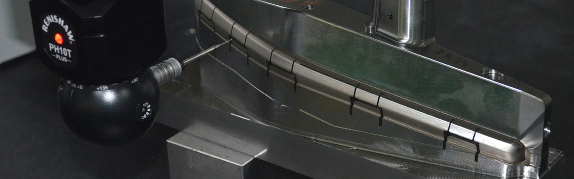
CMM and X-ray inspection — dimensional verification and internal quality assessment
ISO 9001 minimum with IATF 16949 preferred for automotive work
Track record indicators:
Demonstrated experience with your target alloy (aluminum die casting experience does not automatically translate to magnesium capability)
Case studies with parts of similar size, complexity, and quality requirements
References from companies in your industry
Proven export experience — shipping molds or cast parts to your region
| Interval | Action |
|---|---|
| Daily | Inspect cavity surface for heat checking, erosion, or cracking; clean vents; check lubrication |
| Every 10,000 shots | Inspect gate areas for erosion; measure critical cavity dimensions; check ejector system for wear |
| Every 30,000–50,000 shots | Polish cavity surfaces; weld-repair minor cracks; replace worn core pins and ejector pins; check cooling channel flow rates |
| Every 100,000+ shots | Major overhaul — re-machine cavity surfaces, replace worn slides, verify all dimensional tolerances |
Control die temperature tightly — thermal shock is the primary cause of premature heat checking
Use appropriate release agents — minimal but consistent application prevents soldering without excessive buildup
Avoid exceeding recommended shot rate — pushing cycle time too fast increases thermal gradient stress
Plan preventive maintenance proactively rather than waiting for quality issues to signal die wear
Store dies properly between production runs — clean, dry, coated with rust preventive, stored in a climate-controlled area
Die life varies significantly by alloy. For aluminum die casting, a well-maintained H13 mold typically delivers 100,000–200,000 shots, with premium steels (8407, maraging) extending to 300,000–500,000 shots. Zinc die casting molds can exceed 500,000–1,000,000 shots due to lower casting temperature. Magnesium molds have shorter life (50,000–150,000 shots) due to higher thermal and erosive stress.
Yes. Minor heat checking and surface erosion can be polished out. Cracks can be repaired by TIG welding with matching tool steel filler, followed by re-machining and heat treatment. Worn cavity surfaces can be re-machined and shimmmed. However, each repair cycle slightly alters cavity dimensions, so track cumulative repairs against tolerance requirements. For critical parts, plan for cavity insert replacement rather than repeated repair.
As-cast tolerances depend on part size and linear dimension:
| Dimension (mm) | Standard Tolerance | Precision Tolerance |
|---|---|---|
| Up to 25 | ±0.10 | ±0.05 |
| 25–100 | ±0.15 | ±0.08 |
| 100–300 | ±0.25 | ±0.15 |
| 300–600 | ±0.40 | ±0.25 |
Precision tolerances require tighter process control, higher-grade die construction, and more frequent die maintenance. For dimensions tighter than precision tolerance, machining after casting is required.
Die casting excels in medium-to-high volume production (1,000+ parts/year) where complex geometry, thin walls, and good surface finish are needed. Tooling cost is high but amortized over volume. Investment casting offers lower tooling cost and can handle more complex internal geometries, but per-part cost is higher and surface finish is rougher. For simple geometries at low volume, investment casting is typically more economical. For anything above a few hundred parts with moderate complexity, die casting wins on total cost.
Vacuum die casting evacuates air from the mold cavity immediately before injection, reducing gas porosity by 60–90%. It requires a vacuum valve integrated into the mold and a vacuum system connected to the die casting machine. Use vacuum die casting for structural parts subject to fatigue loading, pressure-tight components, and any part that will be heat-treated after casting (heat treatment expands trapped gas, causing surface blistering).
The foundation of a successful die casting project is a thorough part design review conducted jointly between your engineering team and the mold maker. This review — often called a casting feasibility study or DFM for die casting — should address:
Alloy selection based on mechanical, thermal, and corrosion requirements
Wall thickness distribution and transition design for sound casting
Gate and runner layout for balanced fill with minimal porosity
Draft angles (minimum 0.5–1.0° per side for aluminum, 0.25–0.5° for zinc) for clean ejection
Undercut management — side cores, slides, and their impact on tooling cost and cycle time
Tolerance requirements — distinguishing as-cast dimensions from post-machined dimensions
Providing a complete technical data package — 3D model (STEP), 2D drawing with tolerance callouts, target alloy, annual volume, and quality requirements — enables accurate quoting and realistic timeline commitments.
For die casting mould inquiries, casting simulation analysis, and production tooling quotations, contact the engineering team at GMMOLDTECH.

 Call us on:
  Email Us:
  Shengan Building A, Hengzeng Road Chang'an Town Dongguan City,